国际音频协会(AES)第51次会议广州韵奇演讲论文
Liang NaiZhong1 2 Chen Gang1 Wang LiShi1
1 State Key Laboratory of Pulp and Paper Engineering
South China University of Technology
2 GuangZhou YunQi trading Company, Guangzhou, China
Abstract: The properties of loudspeaker cone, such as dynamic Young’s modulus, loss factor, acoustical velocity etc., are very important for a loudspeaker’s cone. They are not only useful for designing and manufacturing loudspeaker system, but also helpful for choosing and optimization of raw materials in cone developing and quality control in cone making process. There are some limitations and errors in all the present methods for measurement of Young’s Modulus and Loss Factor of speaker cone. These present methods can only measure a straight shape sample with equal thickness. Since the speaker cone may have a curved shape often with non-uniform thickness, they can not directly evaluate the actual cone. So it is necessary to develop an approach to more accurately characterize the cone’s Young’s modulus and loss factor.
In this paper we research measurement of the Young’s Modulus and Loss Factor by the method of vibration reed. A measurement system for Young’s Modulus and Loss Factor (MSFYL) is developed.
The innovation of the MSFYL includes two aspects: a three-dimensional automatic guide track is designed. Thus the laser sensor can move at a trajectory the same as the curve of the cone sample. Meanwhile, Young’s Modulus and Loss Factor is measured at each point from upper to the lower end of the sample in a successive automated manner. Then the testing values are transferred into an average, by this way we can modify the inaccuracy caused by non-uniform thickness of the cone sample. During the detecting process, at each particular detecting point, the laser sensor will automatically be adjusted to a place which is perpendicular to the testing sample. Hence, the measurement error caused by the curved shape of the testing cone sample will be avoided.
Key words: loudspeaker cone, Young’s Modulus, Loss factor, curved, non-uniform thickness
0 Introduction
quality of the loudspeaker. In general, the requirements of loudspeaker cone materials should have three characteristics at the same time, namely, (1) low density (2) high mechanical strength, or the material shall have high Young's modulus E, or E /ρ of the material is required to be larger when combining with the first feature (3) with the appropriate damping.
Methods for measuring Young's modulus of materials are divided into two categories, namely, static measurements and dynamic measurements. Static method usually is used for large deformation and room temperature, its disadvantage is, the failure in truly reflecting changes in the material internal structure, and brittle materials (glass, ceramic, etc.) and non-abnormal conditions can not be measured by this method due to large load, slow loading and also relaxation process, meanwhile, static measurement method can not be used to test the material loss factor, while dynamic method can avoid these shortcomings. Dynamic method commonly chooses curved transverse resonance method.
Currently, there are many methods measuring Young's modulus and loss factor, but these are confined to the testing after making loudspeaker cone material into a flat paperboard and thus making relevant qualitative analysis on the cone materials. However, most of loudspeaker cones in actual production have a certain degree of curvature, and various parts of loudspeaker cone have uneven thickness. These test methods have obvious testing errors in testing loudspeaker cone specimens.
Let us describe by taking a paper cone—the main variety of loudspeaker cone, as an example. Due to different papermaking technology of the same cone material ingrediants in the papermaking process, change will occur to fiber shape and internal structure of the cone material. The Young's modulus and loss factor (damping) of molded cone will change accordingly compared to its raw materials. Specifically the same cone material, with different beating degree, different machine’s dredging-pulp vacuum and different thermoform pressure will result in a difference of the Young's modulus and loss factor (damping) of the paper cone produced. Therefor Young's modulus and loss factor (damping) tested simply by making the pulp into a flat paperboard sheet can only be used as a reference for choosing cone materials, but can not be used to guide the design of loudspeaker parameters, otherwise it will create a larger error in loudspeaker design.
The world today is still lack of an instrument that can directly measure the Young's modulus and loss factor (damping) of loudspeaker cone. Development of the instrument with such functions will be of great significance for loudspeaker design and manufacturing, choice of loudspeaker cone materials, and quality control during the loudspeaker cone making process.
In this paper, the author studied the methods measuring Young's modulus and loss factor (damping) of loudspeaker cone, and meanwhile designed a high-precision instrument with the repeatability of test results used for measuring Young's modulus and loss factor (damping) of loudspeaker cone according to non-uniform thickness and bending characteristics of loudspeaker cone.
Testing of Young's modulus of loudspeaker cone uses method of vibration reed by cutting off a rectangular rod-like paper strip from upper to the lower end of the cone as a specimen. As the specimen is very thin and susceptible to load impact, the specimen testing process shall use non-contact method without making any treatment on it. And the specimen is excited by acoustical pressure, the sample vibration signal is detected pneumatically via laser vibration pick-up, the detected signal is input into the computer after treatment, the designed computer software procedures will enable the conversion of data. Under certain conditions, resonance phenomenon will appear when the vibration frequency is equal to the inherent frequency of the specimen, and the vibration amplitude will attain the maximum. As the vibration frequency is related to Young's modulus, Young's modulus of the materials used for the production of rods can be obtained on the basis of thin rods resonance frequency.
Innovation of this study:
Due to the un-uniform thickness of the loudspeaker cone and a certain curvature, testing any point of cone can not represent Young's modulus and loss factor of the cone as a whole. In this paper, the author proposed to use method of vibration reed to measure Young's modulus and loss factor of the loudspeaker cone. Innovation of this method lies in the three-dimensional automatic rail designed on vibration pick-up system part, laser sensor can conduct continuous multi-point measurement for driven by automatic rail from the top to bottom of the cone specimen, the trajectory of the laser sensor shall maintain consistent with the curvature of the specimen, and average all Young's modulus and loss factor values of all measurement points from the top to bottom of the cone specimen, and thus make amendments to the measurement error caused by uneven thickness of the loudspeaker cone. For the curvature specimens testing process from top to bottom, laser sensor does not only maintain the same trajectory as the loudspeaker cone arc, but also automatically detect the vertical distance from the probe to curvature specimen, so that the laser sensor can always conduct signal detection perpendicular to the sample position to reduce the measurement error caused by curvature of loudspeaker cone.
This unique method overcomes the measurement error caused by different Young's modulus and loss factor of various parts due to un-uniform thickness and curvature of loudspeaker cone. Measurement of Young's modulus and loss factor by the method of vibration reed
Young's modulus is an extremely important physical quantity of solid materials, reflecting the resistance to deformation when the object is under external force on a macro level, it is an indispensable physical quantity in the mechanical calculation; reflecting the structure of the material on a micro level, so people have always paid special attention to the determination of Young's modulus. In general, there are two ways for the determination of Young's modulus, namely: static Determination and dynamic Determination. in the case of external conditions (such as temperature) change, and special environment. Dynamic measurement method often proves very beneficial, such as reed vibration method.
As loudspeaker cone fibers have disordered orientation due to free deposition in the wet-end molding process. A long-strip paper sample cut off from the paper cone can be considered as an isotropic thin rod model.
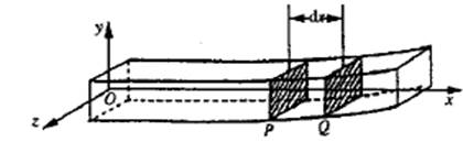
Fig. 1.1 Horizontal Vibration of Rod
Vibration generated due to the force with cyclical changes applied on a plane of slender rod is called as the transverse vibration. Its rod shape is shown as in Figure 2. 1, in the vibration process, each section is subject to the action of torque. According to the literature [3], kinetic equation of the specimen vibration is as follows:
 (1)
(1)
Assuming that the selected materials take the shape of prolate rectangular strip, with the density ρ, length l, making one end fixed (reed) and in free undamped vibration with the frequency![]() . Amplitude in the steady state is only related to x-axis position but has nothing to do with the time t, so that we can conduct variable separation process on the deflection y (x, t), then we can get
. Amplitude in the steady state is only related to x-axis position but has nothing to do with the time t, so that we can conduct variable separation process on the deflection y (x, t), then we can get
y ( x , t) = X ( x ) 〔A co s![]() t + B sin
t + B sin![]() t〕 ( 2)
t〕 ( 2)
Then substitute formula (2) into formula (1), we can obtain

(3)
Then, formula (1) is changed into an ordinary differential equation formula (3). Let

(4)
And then substitute formula (4) into (3), we obtain

(5)
Its solution is ![]() through the following relationship
through the following relationship
(6)
We can obtain the general solution of ordinary differential equation (5)
![]()
(7)
By using the boundary conditions:
Fixed end, x = 0, y = 0 (deflection is 0).

(rotation angel is 0) (8)
Free end,  (bending moment 0),
 (9)
(9)
General solution formula (7) is substituted into boundary condition formula (8), (9), we can obtain
C1 + C3 = 0
C2 + C 4 = 0
 (10)
(10)
This is a linear equation group with four unknown c1, c2, c3, c4, written in determinant form, i.e.
![]()
![]()
1 0 1 0
0 1 0 1 = 0 (11)


After calculating the determinant, we can obtain
![]() (12)
(12)
Formula (12) is actually a vibration equation, by using numerical calculation method, we can get its characteristic solution is as follows:
(13)
… … …
![]()
Here, ![]() corresponds to the grade of vibration,
corresponds to the grade of vibration, ![]() is the Fundamental Vibration,
is the Fundamental Vibration, ![]() ,
,![]() …respectively represent No.1, No. 2 resonance, shown as in Figure 2.3.
…respectively represent No.1, No. 2 resonance, shown as in Figure 2.3.
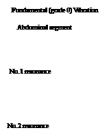
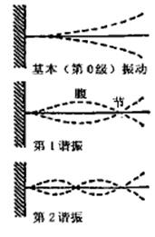
Figure 1.2 Resonance Model
Substitute ![]() into formula (11), we can obtain
into formula (11), we can obtain
![]() (14)
(14)
Or

(15)
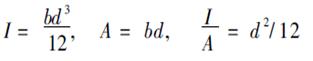
fn is the resonance frequency of rod, for the rectangular cross-section rod of width b, height d, there are the following formulas:
Reed vibration method is to fix one end of the test piece to enable the other end freely in forced vibration, measuring vibration amplitude simultaneously when changing the forced vibration frequency, resonance occurs when the external forced vibration frequency is consistent with natural frequency of the specimen, its amplitude attains maximum. According to formula (15), Young's modulus E of the specimen material can be obtained according to formula (15).
![]() , so the vibration frequency fn (n=0, 1, 2, 3⋯), from formula (20), we can know that
, so the vibration frequency fn (n=0, 1, 2, 3⋯), from formula (20), we can know that ![]() (16)
(16)
Thus, as long as we can measure grade 0 vibration frequency (fundamental frequency) f0, we can calculate the resonance frequency at all levels according to formula (16).
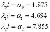
For the convenience of testing, we select grade 0 resonance frequency f0 (fundamental frequency) from fn in formula (15), we know ![]() = 1.875 from formula (20), so formula (21) can be transformed into the following:
= 1.875 from formula (20), so formula (21) can be transformed into the following:
 (17)
(17)
i.e.  (18)
(18)
In fact, substance is not completely elastic body, when we determine the amplitude of the object by changing the forced vibration frequency, its amplitude-frequency curve is shown as in Figure 2.3. Read out f0 and find out △f the difference between two frequencies determining 3dB drop in the curve to define the loss factor:
 (19)
(19)
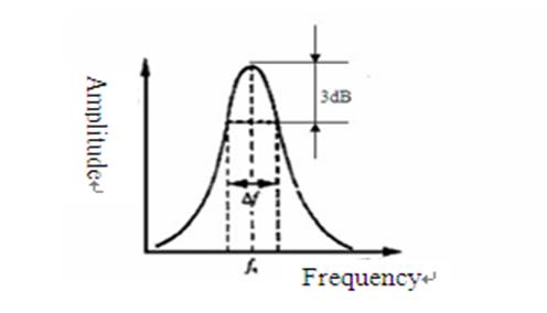
Figure 1.3 Amplitude-Frequency Relationship Curve
In fact, diaphragm materials belong to polymer viscoelastic body. There is phase shift between stress and strain in steady-state vibration, elastic modulus is a complex E *, called as the complex elastic modulus. E*=E1+iE2, in which the real part E1 is dynamic elastic modulus, the imaginary part E2 is dynamic loss modulus of the material. Considering the viscous force of the beam, free vibration equation of the beam is as follows according to the literature [10]:
 (20)
(20)
E* real part and imaginary part is respectively as follows:
 (21)
(21)
 (22)
(22)
The loss factor is:
 (23)
(23)
When giving consideration to the viscous force in the beam, dynamic elastic modulus calculated by
![]() the formula (20) increase a correction term compared to equation (15), formula is closer to reality.
the formula (20) increase a correction term compared to equation (15), formula is closer to reality.
2. Design of measurement system for Young's modulus and loss factor (MSFYL) of the cone
2.1. Work processes and structure of MSFYL:
MSFYL process testing is as follows:
- In the control interface window, enter the test information including the physical data of the testing samples such as length, width, thickness and weight, testing start and stop frequencies, determine the test starting point and test ending point from the cone top to the cone bottom, and the number of points to be tested from the top to the bottom of the cone specimen.
- After restoring displacement sensor to the origin by pressing resetting button. Click the Start button, the system will automatically start the testing.
- After determination of the first testing point from the top of cone specimen, laser displacement sensor will launch upward and downward, backward and forwards, rotary movement to automatically find the vertical distance to the point.
- Then the signal generator will output signal to the loudspeaker, the loudspeaker will issue excitement acoustic wave, cone specimen is excited to produce simple harmonic motion. Displacement sensors will send the detected sample amplitude signal to A/ D converter after having been amplified by the charge amplifier, the analog electrical signals will be converted into digital signals and sent into the CPU for data analysis and plot the amplitude-frequency response curve. Young's modulus and loss factor of the cone specimen can be automatically calculated according to the amplitude-frequency curve.
- Upon the completion of the first point testing, laser sensor automatically walks to the second testing point in accordance with the curvature track of the cone and meanwhile looks for the vertical distance to the point. After completing the action, signal generator will issue the excitation signal to re-start the testing.
- After detecting and calculating Young's modulus and loss factor of the point, the laser displacement sensor will automatically walk to the next point for measurement until the completion of the last one point to be tested.
- Throughout the course of the movement, the trajectory of laser sensor always maintains consistent with the curvature of the cone. And finally plot numerical tables and charts of Young's modulus and loss factor of the detection point, calculate and save the average Young's modulus and loss factor.
Hardware composition of measurement system for Young's modulus and loss factor of paper cone (MSFYL) is shown as below:
![]()
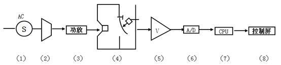
Figure 2.1 MSFYL Testing Hardware System Schematic Diagram
1. Power supply 2. Signal generator 3. Amplifier 4. Sound wave excitement, vibration pick-up system 5. Voltage amplifier 6. A / D converter 7. CPU 8. CPU control panel
Hardware system mainly consists of control cabinet, sound wave excitement part, sample fixture platform, automatic rail system, non-contact laser pick-up part, CPU and monitor composed and other several parts.
2.2. Sound wave excitement and vibration pick-up system
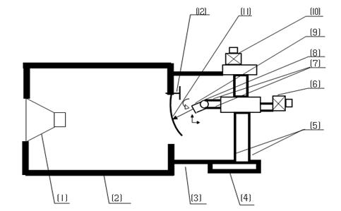
Sound wave excitement part Vibration pick-up part Automatic rail
Figure 2.2 Excitation and Vibration Pick-up Schematic Diagram
1. Loudspeaker 2. Speaker 3. Mounting bracket 4.Rail base 5. Upward and downward rail 6. Stepper motors 7. Left-right moving rail 8. Rotary motion rail 9. Laser displacement sensor 10. Stepper motor 11.Specimen 12. Specimen holder
Sound wave excitement part includes signal generator, amplifier, loudspeakers, speaker fixture, sinusoidal signals produced by signal generator is used as the excitation source, and the amplifier is used to amplify the signal to the rated power of loudspeaker. Sound pressure produced by loudspeaker makes cone specimen generate a certain level of vibration.
The top of automatic rail system is connected with the loudspeaker panel, playing the role of mutual fixation, and a sturdy base in the lower end is fixed on the floor. System consists of rail, stepper motor and limit switch, the entire system includes the three-dimensional guide controlling horizontal movement, upward and downward movement as well as rotational movement, which can provide the path to the displacement sensor for three-dimensional motion. Through the command of control system, automatic rail can make the laser displacement sensor conduct measurement at the position where each test point maintains perpendicular to the cone specimen. When testing different points of the cone specimen, automatic rail will lead the trajectory of displacement sensor to maintain consistent with the curvature of the cone. This is one of the innovative points of this method.
Vibration pick-up system part includes laser displacement sensor, charge amplifier and A / D acquisition card, its role is to convert vibration analog of the cone specimen into the digital and input into the computer for analysis and processing. Vibration pick-up mode of laser displacement sensor is completely non-contact and will not cause impact on the vibration modes of the cone specimen.
Computer hardware system includes CPU central processing unit and monitor, which used for data input for vibration pick-up system, analysis of Young's modulus and loss factor of the loudspeaker cone and provide the relevant functional interface.
3. Software design and testing process of measurement system for Young's modulus and loss factor (MSFYL) of paper cone
This testing system software was designed with TwinCAT PLC programming system of Germany BECKHOFF.
MSFYL software system has main functions as follows:
- Command and control for motion program of the entire system, program running chart is as shown in Figure 4.1.
- 上一篇:扬声器音盆杨氏模量和损耗因数新装置的研发及应用 2016/3/7
- 下一篇:打浆对扬声器纸盆纤维形态及电声性能的影响研究 2016/3/7